
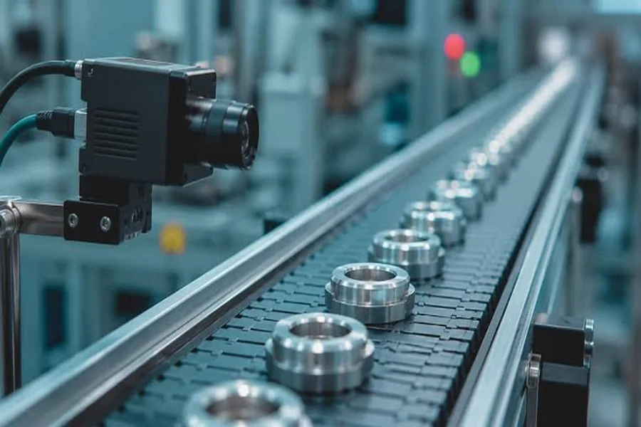
Back-end packaging and test is where semiconductor inspection volumes are highest and margins for error are thinnest. A station that inspects thousands of units per hour cannot afford a camera that needs a long exposure, cannot tolerate motion artefacts in its images, and cannot depend on an illuminator so powerful that it heats the part under test. The 365 nm band solves the optical part of that problem neatly, and then hands the remaining difficulty to the imaging chain.
This article looks at what a 365 nm station actually requires from its camera, and why the specification that matters most is rarely the one printed largest on the datasheet.
Why 365 nm Fits Back-End Work
The 365 nm line is the pragmatic choice for high-volume screening. It sits inside the UVA band, so LEDs are efficient, filters are inexpensive, and fused-silica optics are available off the shelf. Its wavelength is short enough to improve the diffraction limit relative to visible light, which sharpens edges and improves the visibility of fine features such as die-attach fillets, wire-bond tails, and moulding flash. And because it is not a deep-UV band, the optical path does not have to be purged, which keeps the station compact and serviceable.
What 365 nm does not do is generate a strong signal. Reflectance from moulding compound, polyimide, and solder mask is modest, and defects that matter, such as hairline cracks or delamination at an interface, scatter rather than reflect. The camera therefore sees a low-contrast image in a short exposure, which is precisely the regime where sensor quantum efficiency and noise floor decide the outcome.
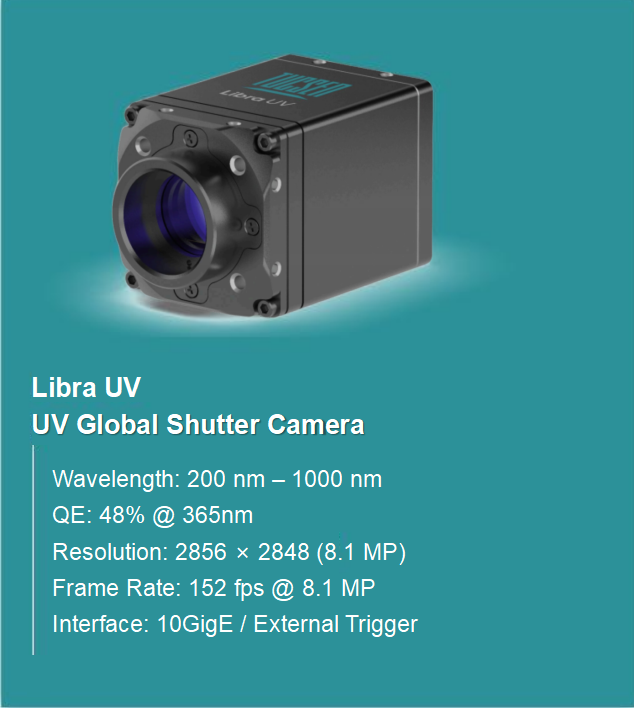
Figure 1: A UV-optimised global shutter camera for high-speed back-end inspection.
The Signal Budget in Practice
A useful way to design the station is to write down the signal budget before choosing hardware. Assume a line moving at 200 mm/s, a field of view of 30 mm, and a requirement to resolve 5-micron defects, which implies a pixel footprint of roughly 1.5 microns on the sample and therefore a short exposure if image motion is to stay below one pixel. Under those assumptions, exposure lands in the tens of microseconds.
In tens of microseconds, even a bright LED delivers only a few hundred photons per pixel at the sensor. A conventional industrial camera with 25% UV quantum efficiency converts that into a signal close to its own read noise, and the resulting image has contrast too low for reliable thresholding. A camera with twice the quantum efficiency doubles the distance between signal and noise floor, which is often the difference between a station that runs at 99.5% yield detection and one that generates false calls all shift.
Why Global Shutter Is Not Optional
Back-end parts move. Whether they are on a walking beam, a rotary table, or a linear motor stage, the sample is in motion during at least part of the exposure, and sometimes the camera itself is moving. A rolling shutter reads rows sequentially, so a part travelling across the field appears sheared. For defect classification this is tolerable in some cases; for dimensional measurement, position feedback, and die-to-die comparison it is not.
The secondary benefit of a global shutter is simpler: it makes trigger timing predictable. When every pixel integrates over the same window, the relationship between encoder position and image content is fixed, which means inspection recipes transfer between machines without recalibration. Stations that mix shutter modes across cameras tend to accumulate small alignment errors that are difficult to diagnose later.
A camera such as the Libra UV illustrates the combination: 48% quantum efficiency at 365 nm, a global shutter, 8.1 megapixels, and 152 fps at full resolution over a 10 GigE link. The frame rate is high enough that the station can run a multi-shot sequence per part, for example bright-field, dark-field, and oblique illumination, without becoming the throughput bottleneck.
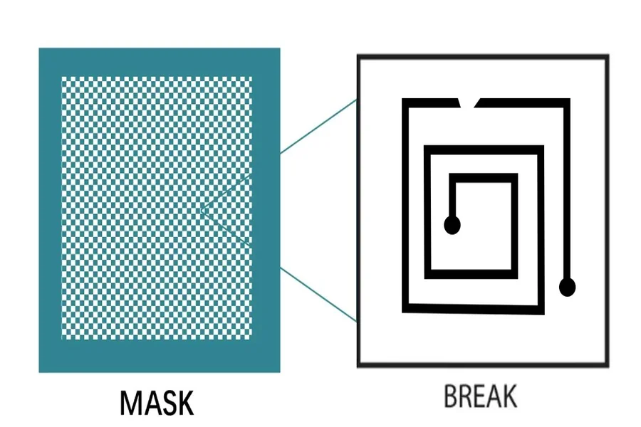
Figure 2: Dark-field defect examples showing the contrast levels a 365 nm station must resolve.
Throughput Comes From the Whole Chain
Camera frame rate is only one term in the throughput equation. The others are illumination intensity, exposure time, data interface bandwidth, and processing latency. A 152 fps camera connected to a host that cannot sustain the corresponding data rate will simply buffer and stall, and a station with brilliant optics but a slow classification step will still be limited by software.
Two habits avoid most of these traps: size the interface for full-resolution streaming rather than a cropped region of interest, and keep the thermal design conservative.
This is where cooling technology stops being a scientific-camera concern and becomes a production concern. A modest, well-controlled temperature offset is worth more than an aggressive one that takes twenty minutes to settle after each power cycle.
Large-Area Coverage Without Losing Resolution
Back-end parts are also getting larger. Panel-level packaging, large interposers, and multi-die modules all push the required field of view upward, and the usual response is to stitch multiple captures, which multiplies acquisition time and adds alignment risk at every seam. An alternative is to accept a larger sensor and a wider lens, which is the logic behind large-area inspection platforms built for high-throughput imaging. The trade-off moves from temporal to spatial: instead of more frames, the station captures more area per frame, and pixel-level uniformity becomes the limiting factor rather than frame rate.
A Short Commissioning Checklist
Before signing off a 365 nm station, verify four things on real product. Confirm that the darkest defect of interest produces a signal at least three times the temporal noise at production exposure. Confirm that image shear is below one pixel at maximum line speed. Confirm that the histogram of a flat reference field does not shift measurably across a four-hour run. And confirm that the camera reaches its specified frame rate at full resolution with the actual cable length in the tool, not on a bench.
Conclusion
A 365 nm back-end station is a signal-budget problem wearing mechanical clothing. The wavelength choice is sound, the optics are mature, and the throughput target is achievable, provided the camera converts available photons efficiently, integrates them simultaneously across the sensor, and holds its noise floor over a full shift. Get those three properties right and the rest of the station becomes straightforward engineering.

Harlod is blogger, creative writer, and SEO specialist dedicated to crafting engaging content. With a passion for storytelling and digital growth, he combines creativity and strategy to help brands connect with audiences.